to stability


Thermowells UNKJ
UNKJ thermowells
Thermowells are designed for protection of CTx 01.10, PRTD (CRTD) 101 (with movable fitting), CTx 01.26, and PRTD (CRTD) 201 (with fixed fitting) or similar temperature sensors from direct medium influence, when the sensor is installed in pressurized vessel, pipeline or other location where additional sensor protection is required.
To provide guaranteed sensor and thermowell contact, it is recommended to mount temperature sensors without mounting elements CTx 01.02, 01.05, 01.99, and PRTD (CRTD) 102, 106 and 108 by means of mounting fitting UNKJ 038 or movable fitting UNKJ 031 (see "UNKJ units and components" section).
Thermowells are manufactured in compliance withTU 4211-011-10854341-13 and production drawings engineered by PC TESEY. Technical specifications determine requirements to structure and dimensions of thermowell made of various materials (steel, ceramics, PTFE). List of materials is given in the Table 1 of this section.
Subject to item 6 of the article 1 of the Federal law dated March 04, 2013, No. 22-FZ "On introducing amendments to the Federal law "On industrial safety of hazardous production facilities", the following amendments were introduced to the article 7 of the Federal law dated July 21, 1997, No. 116-FZ "On industrial safety of hazardous production facilities" (later on - the Federal law No. 22-FZ). The amendments are valid since 01.01.2014:
- Obligatory requirements to technical equipment used at hazardous production facilities, and appraisal forms of equipment compliance to specified obligatory requirements are specified according to the technical regulation legislation of the Russian Federation.
- If the technical regulation does not specify another conformity appraisal form of equipment used at hazardous production facilities, which is an obligatory requirement to such equipment, then the equipment is subject to expert appraisal of industrial safety.
In compliance with Technical Regulation of the Custom Union. "On safety of equipment operating under overpressure" (Technical Regulation of the Custom Union 032/2013), valid till February 01, 2014.
2. This technical regulation covers the following equipment types:
k) equipment elements (assembly units) and its components withstanding the pressure;
11. Equipment safety is provided by means of conformity to safety requirements listed in this section and in enclosure N 2 to the technical regulation during equipment development (engineering) and production (manufacturing): "Requirements to equipment safety during development (engineering) and production (manufacturing)"
Extracts from the enclosure:
1. During equipment development (engineering) it is necessary to calculate equipment durability taking into account projected loads during operation, transportation, handling, installation, and also design load deviations.
13. Equipment durability assessment is based on calculation methods or experimental results without calculations in case if product of maximum permissible operating pressure and equipment capacity value is less than 0.6 MPa*m3, or if product of maximum permissible operating pressure and nominal diameter value is less than 300 MPa*mm.
14. The following calculation methods that can complement each other are used for equipment durability calculation:
a) formulas given in equipment durability calculation standards;
b) stress condition numerical analysis;
c) examination of limit states and fracture mechanics.
Further, in compliance with requirements of the Technical regulation of the Custom Union 032/2013:
37. Equipment being manufactured at the customs territory of the Custom union, is subject to appraisal (confirmation) of conformity to the technical regulation requirements.
38. Appraisal (confirmation) of equipment conformity to the technical regulation requirements is carried out as a state control (inspection) and confirmation of conformity.
40. Confirmation of equipment conformity to the technical regulation requirements (later on - confirmation of conformity) is carried out by means of:
a) qualification executed by accredited certification authority ( conformity appraisal (confirmation) body), specified in the Uniform register of certification authorities and testing laboratories (centres) of the Custom union (later on - certification authority);
43. 3rd and 4th category equipment should be certified.
44. Declaration of compliance or certificate of conformity are the only documents confirming equipment conformity to the technical regulation requirements.
45. To obtain confirmation of conformity, the applicant should prepare a set of equipment documents, which contains:
a) safety case;...
d) strength analysis results;...
n) other documents, that directly or indirectly confirm equipment conformity to the technical regulation requirements (if available).
Thermowells are designed for thermocouple and resistance thermocouple (later on - thermocouple) protection from mechanical and chemical impact of measuring media, when thermocouple is installed in pressurized vessel, at pipeline or at other sites, including sites of 1, 2, 3, and 4 category according to classification of the Technical regulation of the Custom union 032/2013.
Based on the information given above, we believe that thermowells are subject to obligatory certification for conformity to the technical regulation of the Custom union 032/2013.
Dear customers!
To avoid negative consequences concerned with the use of products that do not comply to requirements of the Federal law No. 116 "On industrial safety of hazardous production facilities" and violate existing legislation (articles 1229 and 1358, part 4 of the Civil Code of the Russian Federation), please pay attention to the two important characteristics when selecting thermowell manufacturer:
1. The manufacturer shall have a certificate of thermowell compliance with requirements of TR TS 032/2013, and a set of documents that were the basis for certificate issuing.
This data is available to the public at the site of the Federal Certification Authority (http://fsa.gov.ru/index/staticview/id/70/) in national part of the Uniform register of issued certificates of conformity in standard form. You shall just enter certificate number and/or manufacturer.
As it is almost impossible to carry out thermowell full-scale testing under simultaneous temperature, pressure and medium flow action in testing laboratory conditions, availability of thermowell strength analysis method is an obligatory requirement. In this case tests can be restricted to limited number of equipment samples - typical representatives of the complete assortment. If there is no certificate, safety expert review availability is an obligatory requirement according to the article 7 of the Federal law No. 116-FZ, including amendments valid till 01.01.2014.
2. Coupling design of UNKJ 020 thermowell flange and immersion part is covered by utility model patent No. 39225. Such coupling design allows to increase allowable flow rate up to values given in tables 7.6 and 7.7.
If another manufacturer indicates that his thermowells have allowable flow rate values similar to values of our flanged thermowells, this manufacturer either deludes customers or infringes exclusive rights of PC TESEY.
If the customer buys such flanged thermowells, he either buys products that do not comply to announced characteristics, or also infringes exclusive right of PC TESEY by means of counterfeit goods buying.
Item 2, article 1358, part 4 of the Civil Code of the Russian Federation reads as follows: "Use of an invention, utility model or industrial pattern is considered, particularly:
1) import in the territory of the Russian Federation, production, application, offer for sale, sale, other commercialization or storage for the purposes mentioned above of product which uses invention or utility model...".
Thermowells do not fall within the scope of the Technical regulation of the Custom Union "On mechanism and equipment safety" (TR CU 010/2011), approved by the decision of the Custom union's committee dated 18.10.2011 No.82 (with amendments). Provision of certificate of conformity or declaration of compliance is not required in compliance with the letter of OAO VNIIS No. 101-КС/318 dated 19.03.2014.
THERMOWELL MATERIALS
Table 1 UNKJ thermowell production materials
Material grade |
UNS designation |
Nominal |
Maximum design |
|
12Cr18Ni10Т |
— |
S10 |
700 |
|
08Cr18Ni10Т |
— |
S08 |
|
|
AISI 321 |
S32100 |
S321 |
|
|
10Cr17Ni13М2Т, 08Cr17Ni13М2Т |
— |
S13 |
700 |
|
03Cr17Ni14М3 |
— |
S14 |
450 |
|
AISI 316Н, 316Тi |
S31609, S31635 |
S316 |
800 |
|
AISI 304L |
S30403 |
S304 |
400 |
|
AISI 310 |
S31000 |
Т310 |
800 |
|
10Cr23Ni18, 20Cr23Ni18 |
|
Т18 |
800 |
|
CrNi78Т |
|
Т78 |
900 |
|
Nimonic 75 |
N06075 |
||
|
ХН32Т |
— |
Т32 |
900 |
|
Incoloy 800Н*, 800НТ* |
N08810, N08811 |
I800 |
900 |
|
Incoloy 825* |
N08825 |
I825 |
540 |
|
15Х25Т |
— |
Т00 |
700 |
|
AISI 446 |
S44600 |
Т446 |
|
|
AISI 304L |
N08904 |
T904 |
400 |
|
AISI 904L, 03ХН28МДТ |
— |
Т28 |
400 |
|
12Х1МФ |
— |
SMF |
585 |
|
P91 |
K91560 |
P91 |
650 |
|
Hastelloy C276* |
N10276 |
Н276 |
500 |
|
Hastelloy C22* |
N06022 |
Н22 |
500 |
|
Monel 400* |
N04400 |
М400 |
480 |
|
Inconel 600* |
N06600 |
Т600 |
800 |
|
Inconel 625* |
N06625 |
Т625 |
800 |
|
PTFE-4, |
— |
F |
200 |
|
high-aluminium-oxide ceramic C799 |
— |
C799 |
1200 |
|
reaction bonded silicon carbide SiSiC |
— |
CК90 |
1000 |
|
Syalon 101** |
— |
C101 |
1000 |
|
Syalon 050** |
— |
C050 |
1200 |
|
Syalon 110** |
— |
C110 |
1200 |
|
* Hastelloy — registered trademark of Haynes International, |
|||
Table 2 - Materials for elevated temperatures
Material grade |
Material designation |
Maximum |
Permissible long-term operating temperature |
Purpose |
|
10Cr23Ni18, 20Cr23Ni18 |
Т18 |
1050 |
1000 |
Recommended for sulphur-containing media Thermowells. |
|
AISI 310 |
Т310 |
1100 |
||
|
AISI 446 |
Т446 |
1100 |
Recommended for sulphur-containing media Increased sulphur resistance as compared to Т18, Т310. |
|
|
15Х25Т |
Т00 |
1050 |
||
|
CrNi78Т |
Т78 |
1150°С |
1100 |
Recommended for oxidizing media without sulphur. Thermowells for flame tubes, combustion chambers, turbine chambers. |
|
ХН45Ю |
Т45 |
1300°С |
1250 |
|
|
Inconel 600 |
Т600 |
1150°С |
1100 |
|
|
Inconel 625 |
Т625 |
1100°С |
1100 |
Specified lifetime:
– 10 years under operating temperature, which does not exceed maximum design operating temperature stated in the table 1, and on condition, that not more than 2/3 of protection tube length is subject to force medium impact, and that operating flow rate does not exceed 80% of maximum design value;
– 5 years under operating temperature which does not exceed maximum design operating temperature stated in the table 1, in case of complete thermowell tube immersion in mobile media and/or operation under flow rate exceeding 80% of maximum design value;
– 1 year under operating temperature, which corresponds to allowable long-term operation values stated in the table 2.
Specified life time is not rated for operating conditions in chemically non-aggressive media to thermowell material.
Thermowell guarantee period is 4 years from the date of commissioning, but not longer that specified life time mentioned above. Product replacement under warranty is carried out on the basis and in compliance with the procedure established in certificate and operation manual.
Guaranteed shelf life is not limited.
TERMS AND DEFINITIONS
Nominal (rated) pressure PN (GOST 26349-84)– is the maximum excessive operating pressure at operating temperature 20°С, under which it is possible to provide design life time of pipeline connectors and fittings with specified dimensions based on durability calculations for the selected materials and their strength characteristics under temperature equal to 20°С.
Operating pressure Pp (GOST 356-80)– is the maximum excessive pressure, under which it is possible to provide specified mode of fitting and pipeline components operation.
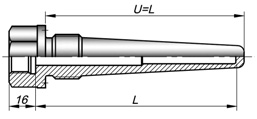
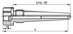
Insertion lengthL – thermowell part from internal working edge surface to thermocouple sealing. Thermowell insertion length is equal to the probe length of installed thermocouple.
Immersion length U – distance between working edge and bearing (sealing) thermowell surface.
THERMOWELL TECHNICAL SPECIFICATION
.jpg)
.jpg) 1. Thermowells are nonrepairable and nonrestorable items.
1. Thermowells are nonrepairable and nonrestorable items.
2. UNKJ 011; 014; 114; 015; 016; 021; 022; 023; 026 thermowells are equipped with fitting thread: metric according to GOST 24705, straight pipe according to GOST 6357, British taper according to GOST 6111, and metric taper thread according to GOST 25229. Internal connecting thread N (M20x1.5 by default) can be made according to Russian or foreign standards at the customer's request.
3. UNKJ 019, 020, 024, 124 thermowell flanges have sealing surfaces and connecting dimensions according to GOST 12815, GOST R 54432, and also according to ASME B16.5 or DIN EN 1092-1 standards. Customized flanges can be produced on the basis of the Customer's technical specification. Design documents will be developed and agreed in compliance with the established procedure.
4. Design pressure values for all thermowells comply to durability criteria according to ASME BPVC Section VIII, part 1 UG-28 and ASME PTC 19.3 TW-2010.
5. Thermowell is welded according to STP 015-14, welding joint dimensions conform to GOST 14771-76.
5. Thermowells of all modifications are leak-proof.
6. Thermowell marking contains thermowell designation, factory number, production date. Flanged thermowells additionally bear logotype and flange PN, DN.
7. Immersion part of steel thermowell can have an additional hard wear-resistant and corrosion-resistant coating. Spray-fusing coating method is based on self-fluxing alloys, that contain borium and silicon. Borosilicates, that are formed during self-fluxing alloy melting, fix iron, nickel and chromium oxides, and put them to the surface. This feature allows to apply rather thick coats.
Due to chromium boride and high microhardness, fused coating is resistant to abrasion and erosion, and also highly wear-resistant. This value is approximately ten times larger than for steel.It is especially important that fused coating of self-fluxing powders is heat-resistant and chemically-resistant in many aggressive media: sweet and sea water, moisture and superheated steam, hydrochloric acid, acetic acid, fluohydric acid, boric acid and chromic acid, caustic soda, potash lye, hydrogen sulphide, glass bath, and other.As initial hardness of such coatings stays stable under heating up to 500-600°С, they are used under high temperature as heat-resistant coatings. Fused layer density is 7,6 - 7,9 g/cm3.
OPERATION GUIDELINES
1. Thermowell installation at site should be carried out in compliance with operation manual of the equipment, where thermowell is mounted. Sealing gaskets are not included, but can be supplied at request.
2. Tube wall thickness can be reduced during thermowell operation in chemically-active and corrosive medium.
IT IS FORBIDDEN TO USE THERMOWELL WHICH HAS SIGNS OF CORROSION AND EROSION MEDIUM ACTION.
Method MRP UNKJ-13 allows to calculate thermowell strength properties taking into account tube wall thickness reduction value. To obtain permissible rate values calculation according to method MRP UNKJ-13 please contact the manufacturer.
Note — 1 mm tube wall thinning out requires 2 times reduction of maximum allowable operating pressure for UNKJ 014 thermowell and 1,5 time reduction for UNKJ 016, 026, 018, 020, 024 thermowells, and 40% reduction of limit flow rate. (Values are given for the reference).
3. Thermowell should be operated under flow rate which does not exceed values determined according to MRP UNKJ-13. Maximum medium flow rate, nominal (rated) pressure and operating pressure are determined by the method on the basis of thermowell static strength provision. Long-term material strength is taken into account for maximum flow rate calculation. Limit operating pressure of UNKJ 019, 020, 024, and 124 flanged thermowell is limited by flange strength. Allowable pressure ranges for thermowell operation are given in the tables 6.1-6.9. Reference permissible flow rate values for main modifications of thermowells being operated in media with density 10, 100, 1000 kg/m3 and temperature up to 600C under complete immersion (without including connection port/weldolet) shown in the picture below, are given in the tables 7.1-7.7.
|
|
|
|
а) |
b) |
|
а — threaded thermowell; б — flange thermowell |
|
.jpg)
.jpg)
If medium flow rate and density values at site are lower than values given in tables 7.1-7.7, thermowell can be operated without additional adjustments. If density and/or flow rate at site is higher than reference value, it is recommended to contact the manufacturer to obtain calculation of permissible flow rate values according to method MRP UNKJ-13 for thermowell operating conditions.
ATTENTION: To carry out calculations it is necessary to indicate thermowell model and operating conditions, namely: density, pressure and medium temperature, length of thermowell part which is immersed in flow.
4. Not-recommended flow rate range is a range where thermowell fatigue breakdown is possible due to protection tube resonant vibration caused by vortex shedding at cross flow. Specified range is determined as a ratio of protection tube own vibration frequency and forced vibration frequency. The range depends on medium physical properties (density, viscosity, Reynold's number).
ATTENTION: not recommended flow rate range can be determined solely for real operating conditions! (values stated in tables 7.1-7.7 are given illustratively to demonstrate their presence for specific modifications.
THERMOWELL DESIGN FEATURES
Screw-in thermowell versions depending on sealing type at site
Table 3
Connecting thread |
Version A |
Version B |
Version C |
|||||||
|
with groove to GOST 10549 |
with tapered thread |
according to GOST 22526 |
according to OST 26.260.460 |
|||||||
|
|
|
|
|
|
||||||
|
Pic. 1 |
Pic. 2 |
Pic. 3 |
Pic. 4 |
Pic. 5 |
||||||
|
M |
Dm, mm |
ℓP, mm |
Dm, mm |
ℓP, mm |
К |
ℓP min , mm |
Dm, mm |
ℓP, mm |
Dm, mm |
ℓP, mm |
|
М20х1,5 |
31 |
17 |
— |
½ |
21.0 |
25 |
14 |
31 |
17 |
|
|
G1/2 |
31 |
17 |
¾ |
21.5 |
26 |
14 |
31 |
17 |
||
|
G3/4 |
— |
38 |
22 |
1 |
26.5 |
32 |
16 |
36 |
22 |
|
|
М27х2 |
38 |
22 |
1½ |
27.5 |
32 |
16 |
36 |
22 |
||
|
G1 |
48 |
32 |
— |
39 |
18 |
43 |
32 |
|||
|
М33х2 |
48 |
32 |
39 |
18 |
43 |
32 |
||||
.jpg)
.jpg)
.jpg)
.jpg)
.jpg)
Design depending on sensor seal inside thermowell
Please not that thermowell fitting length is measured from sensor sealing surface, and depends from version, see table 3. Thermowells for sensors with tapered connecting thread are of version Нaccording to sensor sealing type¾ for fixed fitting (see designation code for every thermowell modification, field 7).
Table 4
Fitting length measuring example for a sensor with moveable fitting CTx sensors:01.03; 01.07; 01.10; 02.10; PRTD (CRTD): 101; 103; 105; 107 |
Fitting length measuring example for a sensor |
|
|
|
Versions of flange sealing faces
Table 5
Standard |
version |
|||||
|
connecting raised |
raised face flange |
female flange |
tongue flange |
groove flange |
oval joint |
|
|
GOST 12815 |
1 |
2 |
3 |
4 |
5 |
7 |
|
GOST R 54432 |
В |
Е |
F |
C, L |
D, M |
J |
|
ASME B 16.5 |
RF |
LM; SM |
LF; SF |
LT; ST |
LG; SG |
RTJ |
|
DIN EN 1092-1 |
Type B |
Type E |
Type F |
Type C |
Type D |
Type H |
|
Sealing face draft |
|
|
|
|
|
|
Thermowell over pressure
Table 6.1 Over pressure for thermowell made of 08Cr18Ni10T, 12Cr18Ni10T steel according to GOST 356
Nominal (rated) pressure PN, MPa (kgf/cm2) |
Working pressure Pр under maximum medium temperature, MPa (kgf/cm2) |
||||
|
20°С |
200°С |
400°С |
520°С |
610°С |
700°С |
|
1,00 (10.0) |
1,00 (10.0) |
0,75 (7.5) |
0,58 (5.8) |
0,42 (4.2) |
0,20 (2.0) |
|
1,60 (16.0) |
1,60 (16.0) |
1,20 (12.0) |
0,90 (9.0) |
0,62 (6.2) |
0,32 (3.2) |
|
2,50 (25.0) |
2,50 (25.0) |
1,90 (19.0) |
1,50 (15.0) |
1,00 (10.0) |
0,50 (5.0) |
|
4,00 (40.0) |
4,00 (40.0) |
3,00 (30.0) |
2,30 (23.0) |
1,60 (16.0) |
0,80 (8.0) |
|
6,30 (63.0) |
6,30 (63.0) |
4,80 (48.0) |
3,70 (37.0) |
2,50 (25.0) |
1,30 (13.0) |
|
10,00 (100.0) |
10,00 (100.0) |
7,50 (75.0) |
5,80 (58.0) |
4,20 (42.0) |
2,00 (20.0) |
|
16,00 (160.0) |
16,00 (160.0) |
12,00 (120.0) |
9,00 (90.0) |
6,20 (62.0) |
3,20 (32.0) |
|
20,00 (200.0) |
20,00 (200.0) |
15,00 (150.0) |
11,50 (115.0) |
8,40 (84.0) |
4,00 (40.0) |
|
25,00 (250.0) |
25,00 (250.0) |
19,00 (190.0) |
15,00 (150.0) |
10,00 (100.0) |
5,00 (50.0) |
|
32,00 (320.0) |
32,00 (320.0) |
24,00 (240.0) |
17,00 (170.0) |
12,40 (124.0) |
6,40 (64.0) |
|
40,00 (400.0) |
40,00 (400.0) |
30,00 (300.0) |
23,00 (230.0) |
16,00 (160.0) |
8,00 (80.0) |
|
50,00 (500.0) |
50,00 (500.0) |
37,00 (370.0) |
29,00 (290.0) |
21,00 (210.0) |
10,00 (100.0) |
|
80,00 (800.0) |
80,00 (800.0) |
60,00 (600.0) |
46,00 (460.0) |
32,00 (320.0) |
16,40 (164.0) |
Table 6.2 Over pressure for thermowell made of 12Cr1MF steel according to GOST 356
Nominal (rated) pressure PN, MPa (kgf/cm2) |
Working pressure Pр under maximum medium temperature, MPa (kgf/cm2) |
||||
|
20°С |
200°С |
320°С |
450°С |
510°С |
570°С |
|
40,00 (400.0) |
40,00 (400.0) |
35,00 (350.0) |
30,00 (300.0) |
23,00 (230.0) |
12,00 (120.0) |
|
50,00 (500.0) |
50,00 (500.0) |
45,00 (450.0) |
37,00 (370.0) |
29,00 (290.0) |
15,00 (150.0) |
|
80,00 (800.0) |
80,00 (800.0) |
70,00 (700.0) |
60,00 (600.0) |
46,00 (460.0) |
24,00 (240.0) |
Table 6.3 Over pressure for flanged thermowell with sealing face according to ASME B16.5 made of AISI 321 steel
Temperature, °С |
Over pressure, MPa (kgf/cm2) |
||||||
|
Flange class according to ASME B16.5 |
|||||||
|
150 |
300 |
400 |
600 |
900 |
1500 |
2500 |
|
|
-29 to 38 |
1.94 |
5.06 |
6.75 |
10.12 |
15.18 |
25.31 |
42.18 |
|
(19,40) |
(50,60) |
(67,50) |
(101,20) |
(151,80) |
(253,10) |
(421,80) |
|
|
200 |
1.41 |
3.90 |
5.21 |
7.81 |
11.72 |
19.53 |
32.54 |
|
(14,10) |
(39,00) |
(52,10) |
(78,10) |
(117,20) |
(195,30) |
(325,40) |
|
|
400 |
0.66 |
3.20 |
4.29 |
6.44 |
9.66 |
16.10 |
26.84 |
|
(6,60) |
(32,00) |
(42,90) |
(64,40) |
(96,60) |
(161,00) |
(268,40) |
|
|
500 |
0.29 |
2.87 |
3.83 |
5.76 |
8.64 |
14.37 |
23.96 |
|
(2,90) |
(28,70) |
(38,30) |
(57,60) |
(86,40) |
(143,70) |
(239,60) |
|
|
600 |
— |
2.07 |
2.75 |
4.13 |
6.20 |
10.33 |
17.2 |
|
(20,70) |
(27,50) |
(41,30) |
(62,00) |
(103,30) |
(172,23) |
||
|
700 |
— |
0.80 |
1.07 |
1.61 |
2.42 |
4.03 |
6.72 |
|
(8,00) |
(10,70) |
(16,10) |
(24,20) |
(40,30) |
(67,20) |
||
Table 6.4 Over pressure for flanged thermowell with sealing face according to ASME B16.5 made of AISI 316Ti, AISI 316H steel
Temperature, °С |
Over pressure, MPa (kgf/cm2) |
||||||
|
Flange class according to ASME B16.5 |
|||||||
|
150 |
300 |
400 |
600 |
900 |
1500 |
2500 |
|
|
-29 to 38 |
1.94 |
5.06 |
6.75 |
10.13 |
15.18 |
25.31 |
42.19 |
|
(19,40) |
(50,60) |
(67,50) |
(101,30) |
(151,80) |
(253,10) |
(421,90) |
|
|
200 |
1.40 |
3.64 |
4.85 |
7.27 |
10.91 |
18.18 |
30.31 |
|
(14,0) |
(36,40) |
(48,50) |
(72,70) |
(109,10) |
(181,80) |
(303,10) |
|
|
400 |
0.66 |
3.00 |
4.01 |
6.01 |
9.00 |
15.01 |
25.01 |
|
(6,60) |
(30,00) |
(40,10) |
(60,10) |
(90,00) |
(150,10) |
(250,10) |
|
|
500 |
0.29 |
2.88 |
3.84 |
5.76 |
8.64 |
14.37 |
23.96 |
|
(2,90) |
(28,80) |
(38,40) |
(57,60) |
(86,40) |
(143,70) |
(239,60) |
|
|
600 |
— |
2.03 |
2.70 |
4.06 |
6.09 |
10.15 |
16.92 |
|
(20,30) |
(27,00) |
(40,60) |
(60,90) |
(101,50) |
(169,20) |
||
|
700 |
— |
0.86 |
1.14 |
1.71 |
2.56 |
4.27 |
7.12 |
|
(8,60) |
(11,40) |
(17,10) |
(25,60) |
(42,70) |
(71,20) |
||
|
800 |
— |
0.36 |
0.49 |
0.71 |
1.07 |
1.77 |
2.98 |
|
(3,60) |
(4,90) |
(7,10) |
(10,70) |
(17,70) |
(29,80) |
||
Table 6.5 Over pressure for flanged thermowell with sealing face according to ASME B16.5 made of AISI 310S steel
Temperature, °С |
Over pressure, MPa (kgf/cm2) |
||||||
|
Flange class according to ASME B16.5 |
|||||||
|
150 |
300 |
400 |
600 |
900 |
1500 |
2500 |
|
|
-29 to 38 |
1.94 |
5.06 |
6.75 |
10.13 |
15.18 |
25.31 |
42.19 |
|
(19,40) |
(50,60) |
(67,50) |
(101,30) |
(151,80) |
(253,10) |
(421,90) |
|
|
200 |
1.41 |
3.84 |
5.11 |
7.67 |
11.50 |
19.17 |
31.96 |
|
(14,10) |
(38,40) |
(51,10) |
(76,70) |
(115,00) |
(191,70) |
(319,60) |
|
|
400 |
0.66 |
3.30 |
4.40 |
6.61 |
9.920 |
16.53 |
27.55 |
|
(6,60) |
(33,00) |
(44,00) |
(66,10) |
(99,20) |
(165,30) |
(275,50) |
|
|
500 |
0.29 |
2.88 |
3.84 |
5.76 |
8.64 |
14.37 |
23.96 |
|
(2,90) |
(28,80) |
(38,40) |
(57,60) |
(86,40) |
(143,70) |
(239,60) |
|
|
600 |
— |
1.71 |
2.29 |
3.42 |
5.13 |
8.56 |
14.26 |
|
(17,10) |
(22,90) |
(34,20) |
(51,30) |
(85,60) |
(142,60) |
||
|
700 |
— |
0.56 |
0.75 |
1.12 |
1.68 |
2.81 |
4.68 |
|
(5,60) |
(7,50) |
(11,20) |
(16,80) |
(28,10) |
(46,80) |
||
|
800 |
— |
0.22 |
0.29 |
0.42 |
0.63 |
1.05 |
1.75 |
|
(2,20) |
(2,90) |
(4,20) |
(6,30) |
(10,50) |
(17,50) |
||
Table 6.6 Over pressure for flanged thermowell with sealing face according to ASME B16.5 made of Monel 400
Temperature, °С |
Over pressure, MPa (kgf/cm2) |
||||||
|
Flange class according to ASME B16.5 |
|||||||
|
150 |
300 |
400 |
600 |
900 |
1500 |
2500 |
|
|
-29 to 38 |
1.62 |
4.22 |
5.63 |
8.43 |
12.66 |
21.09 |
35.15 |
|
(16,20) |
(42,20) |
(56,30) |
(84,30) |
(126,60) |
(210,90) |
(351,50) |
|
|
100 |
1.41 |
3.66 |
4.89 |
7.33 |
10.99 |
18.33 |
30.54 |
|
(14,10) |
(36,60) |
(48,90) |
(73,30) |
(109,90) |
(183,30) |
(305,40) |
|
|
200 |
1.28 |
3.34 |
4.45 |
6.67 |
10.00 |
16.67 |
27.78 |
|
(12,80) |
(33,40) |
(44,50) |
(66,70) |
(100,00) |
(166,70) |
(277,80) |
|
|
300 |
1.04 |
3.33 |
4.40 |
6.65 |
9.97 |
16.62 |
27.71 |
|
(10,40) |
(33,30) |
(44,40) |
(66,50) |
(99,70) |
(166,20) |
(277,10) |
|
|
375 |
0.76 |
3.30 |
4.41 |
6.61 |
9.91 |
16.51 |
27.52 |
|
(7,60) |
(33,00) |
(44,10) |
(66,10) |
(99,10) |
(165,10) |
(275,20) |
|
|
400 |
0.66 |
3.27 |
4.36 |
6.55 |
9.81 |
16.36 |
27.27 |
|
(6,60) |
(32,70) |
(43,60) |
(65,50) |
(98,10) |
(163,60) |
(272,70) |
|
|
475 |
0.38 |
2.12 |
2.83 |
4.23 |
6.35 |
10.59 |
17.64 |
|
(3,80) |
(21,20) |
(28,30) |
(42,30) |
(63,50) |
(105,90) |
(176,40) |
|
Table 6.7 Over pressure for flanged thermowell with sealing face according to ASME B16.5 made of Incoloy 800 steel
Temperature, °С |
Over pressure, MPa (kgf/cm2) |
||||||
|
Flange class according to ASME B16.5 |
|||||||
|
150 |
300 |
400 |
600 |
900 |
1500 |
2500 |
|
|
-29 to 38 |
1.62 |
4.22 |
5.63 |
8.43 |
12.66 |
21.09 |
35.15 |
|
(16,20) |
(42,20) |
(56,30) |
(84,30) |
(126,60) |
(210,90) |
(351,50) |
|
|
200 |
1.30 |
3.46 |
4.61 |
6.92 |
10.38 |
17.29 |
28.83 |
|
(13,30) |
(34,60) |
(46,10) |
(69,20) |
(103,80) |
(172,90) |
(288,30) |
|
|
400 |
0.66 |
2.89 |
3.85 |
5.76 |
8.65 |
14.41 |
24.03 |
|
(6,60) |
(28,90) |
(38,50) |
(57,60) |
(86,50) |
(144,10) |
(240,30) |
|
|
500 |
0.29 |
2.68 |
3.58 |
5.36 |
8.06 |
13.42 |
22.37 |
|
(2,90) |
(26,80) |
(35,80) |
(53,60) |
(80,60) |
(134,20) |
(223,70) |
|
|
600 |
— |
2.20 |
2.90 |
4.38 |
6.55 |
10.91 |
18.20 |
|
(22,00) |
(29,20) |
(43,80) |
(65,50) |
(109,10) |
(182,00) |
||
|
700 |
— |
1.03 |
1.37 |
2.04 |
3.04 |
5.07 |
8.47 |
|
(10,30) |
(13,70) |
(20,40) |
(30,40) |
(50,70) |
(84,70) |
||
|
800 |
— |
0.36 |
0.49 |
0.71 |
1.07 |
1.78 |
2.98 |
|
(3,60) |
(4,90) |
(7,10) |
(10,70) |
(17,80) |
(29,80) |
||
Table 6.8 Over pressure for flanged thermowell with sealing face according to ASME B16.5 made of Hastelloy C-276, Inconel 625, Incoloy 825
Temperature, °С |
Over pressure, MPa (kgf/cm2) |
||||||
|
Flange class according to ASME B16.5 |
|||||||
|
150 |
300 |
400 |
600 |
900 |
1500 |
2500 |
|
|
-29 to 38 |
2.04 |
5.27 |
7.03 |
10.54 |
18.52 |
26.37 |
43.94 |
|
(20,40) |
(52,70) |
(70,30) |
(105,40) |
(158,20) |
(263,70) |
(439,40) |
|
|
200 |
1.41 |
4.93 |
6.58 |
9.86 |
14.79 |
24.65 |
41.07 |
|
(14,10) |
(49,30) |
(65,80) |
(98,60) |
(147,90) |
(246,50) |
(410,70) |
|
|
400 |
1.04 |
4.38 |
5.81 |
8.74 |
13.11 |
21.86 |
36.41 |
|
(10,40) |
(43,80) |
(58,10) |
(87,40) |
(131,10) |
(218,60) |
(364,10) |
|
|
500 |
0.66 |
3.72 |
4.99 |
7.45 |
11.20 |
18.67 |
31.09 |
|
(6,60) |
(37,20) |
(49,90) |
(74,50) |
(112,00) |
(186,70) |
(310,90) |
|
|
600 |
0.29 |
2.88 |
3.84 |
5.76 |
8.64 |
14.37 |
23.96 |
|
(2,90) |
(28,80) |
(38,40) |
(57,60) |
(86,40) |
(143,70) |
(239,60) |
|
|
700 |
— |
2.20 |
2.92 |
4.38 |
6.55 |
10.91 |
18.20 |
|
(22,00) |
(29,20) |
(43,80) |
(65,50) |
(109,10) |
(182,00) |
||
|
800 |
— |
0.90 |
1.19 |
1.79 |
2.68 |
4.47 |
7.44 |
|
(9,00) |
(11,90) |
(17,90) |
(26,80) |
(44,70) |
(74,40) |
||
Table 6.9 Over pressure for flanged thermowell with sealing face according to ASME B16.5 made of AISI 904L steel
Temperature, °С |
Over pressure, MPa (kgf/cm2) |
||||||
|
Flange class according to ASME B16.5 |
|||||||
|
150 |
300 |
400 |
600 |
900 |
1500 |
2500 |
|
|
-29 to 38 |
2.01 |
5.23 |
6.98 |
10.46 |
15.69 |
26.16 |
43.59 |
|
(20,10) |
(52,30) |
(69,80) |
(104,60) |
(156,90) |
(261,60) |
(435,90) |
|
|
100 |
1.60 |
4.19 |
5.58 |
8.37 |
12.56 |
20.94 |
34.88 |
|
(16,00) |
(41,90) |
(55,80) |
(83,70) |
(125,60) |
(209,40) |
(348,80) |
|
|
200 |
1.36 |
3.54 |
4.71 |
7.07 |
10.60 |
17.68 |
29.46 |
|
(13,60) |
(35,40) |
(47,10) |
(70,70) |
(106,00) |
(176,80) |
(294,60) |
|
|
300 |
1.04 |
3.06 |
4.08 |
6.12 |
9.18 |
15.31 |
25.50 |
|
(10,40) |
(30,60) |
(40,80) |
(61,20) |
(91,80) |
(153,10) |
(255,00) |
|
|
375 |
0.76 |
2.88 |
3.84 |
5.76 |
8.64 |
14.40 |
24.00 |
|
(7,60) |
(28,80) |
(38,40) |
(57,60) |
(86,40) |
(144,00) |
(240,00) |
|
Reference permissible flow rate values for principal thermowell modifications (for complete immersion in medium)
Table 7.1 Permissible flow rate for thermowell UNKJ 015 made of steel 12Cr18Ni10Т
Thermowell diameter, mm |
Nominal pressure PN, MPa (kgf/cm2) |
Temperature, °С |
Medium density, kg/m3 |
Probe length, L, mm |
||||||||||
|
80-160 |
200 |
250 |
320 |
400 |
500 |
630-1000 |
1250-2000 |
2500 |
3150 |
|||||
|
Permissible flow rate, m/s |
||||||||||||||
|
14 |
20,0 (200) |
20 – 400 |
1000 |
6.8 |
5.2 |
4.2 |
3.2 |
2.4 |
1.9 |
0.9 |
0.4 |
— |
— |
|
|
100 |
21 |
16 |
13 |
10 |
8 |
6.3 |
3.0 |
1.5 |
1 |
1 |
||||
|
10 |
68 |
49 |
42 |
32 |
24 |
19 |
9.0 |
4.0 |
4 |
3 |
||||
|
400 – 600 |
1000 |
3.9 |
2.9 |
2.3 |
1.9 |
1.4 |
1.1 |
0.5 |
0.2 |
— |
— |
|||
|
100 |
12.4 |
9.6 |
7.4 |
5.9 |
4.6 |
3.7 |
2.0 |
0.8 |
1 |
1 |
||||
|
10 |
39 |
29 |
23 |
19 |
14 |
11 |
5.0 |
3.0 |
3 |
2 |
||||
|
not recommended velocity range, m/s |
28-53 |
17-32 |
11-20 |
5.5-12 |
3.5-7.5 |
2.2-4.7 |
0.5-1.2 |
0.13-0.29 |
— |
— |
||||
|
16 |
20,0 (200) |
20 – 400 |
1000 |
7.4 |
6 |
4.6 |
3.6 |
2.8 |
2.2 |
1.1 |
0.6 |
— |
— |
|
|
100 |
24 |
19 |
15 |
11 |
9 |
7 |
3.5 |
1.8 |
1 |
1 |
||||
|
10 |
74 |
60 |
46 |
36 |
28 |
22 |
11 |
5.5 |
5 |
4 |
||||
|
400 – 600 |
1000 |
4.3 |
3.3 |
2.6 |
2 |
1.6 |
1.3 |
0.6 |
0.3 |
— |
— |
|||
|
100 |
13.6 |
10.5 |
8.4 |
6.5 |
5 |
4 |
2 |
1 |
1 |
1 |
||||
|
10 |
43 |
33 |
26 |
20 |
16 |
13 |
6 |
3 |
3 |
3 |
||||
|
not recommended velocity range, m/s |
– |
22-44 |
15-27 |
7-16 |
4.5-10 |
3-6.5 |
0.7-1.6 |
0.2-0.4 |
— |
— |
||||
|
20 |
20,0 (200) |
20 – 400 |
1000 |
9.8 |
7.4 |
6 |
4.6 |
3.5 |
2.8 |
1.4 |
0.7 |
1 |
— |
|
|
100 |
31 |
24 |
19 |
14 |
11 |
8.8 |
4.4 |
2.2 |
2 |
1 |
||||
|
10 |
98 |
74 |
60 |
45 |
35 |
28 |
14 |
6.6 |
6 |
4 |
||||
|
400 – 600 |
1000 |
5.6 |
4.3 |
3.4 |
2.6 |
2 |
1.6 |
0.8 |
0.4 |
— |
— |
|||
|
100 |
17 |
13.6 |
10.5 |
8 |
6.5 |
5 |
2.5 |
1.3 |
1 |
1 |
||||
|
10 |
56 |
43 |
34 |
26 |
20 |
15 |
7.8 |
4 |
4 |
3 |
||||
|
not recommended velocity range, m/s |
– |
39-73 |
24-45 |
14-26 |
9-16 |
5-10 |
1.1-2.4 |
0.3-0.6 |
— |
— |
||||
Table 7.2 Permissible flow rate for thermowell UNKJ 014 made of steel 12Cr18Ni10Т
|
Thermowell diameter, mm |
Nominal pressure PN, MPa (kgf/cm2) |
Temperature, ºС |
Medium density, kg/m3 |
Probe length, L, mm |
||||||||||
|
120 |
160 |
200 |
250 |
320 |
400 |
500 |
630 |
800 |
1000 |
1250 |
||||
|
Permissible flow rate, m/s (not recommended velocity range, m/s) |
||||||||||||||
|
16 |
32,0 (320) |
20 – 400 |
1000 |
11.8 |
8.5 |
6.6 |
5.2 |
4 |
3.1 |
2.5 |
1.9 |
1.5 |
1.2 |
0.9 |
|
(1,1-2) |
(0,7-1.2) |
(0,4-0.8) |
||||||||||||
|
100 |
37.3 |
26.8 |
20.9 |
16.4 |
12.6 |
10 |
7.9 |
6.2 |
4.9 |
3.9 |
3.1 |
|||
|
(13-25) |
(8-15) |
(5-10) |
(3-6) |
(2-4) |
(1-2) |
(0,7-1.4) |
(0,5-0.9) |
|||||||
|
10 |
117 |
84 |
66.3 |
52.1 |
40.1 |
31 |
25.1 |
19.8 |
15.7 |
12.3 |
9.8 |
|||
|
(71-133) |
(37-69) |
(22-42) |
(14-26) |
(8-15) |
(5-10) |
(3-6) |
|
(1-3) |
(0,8-1.4) |
(0,5-0.9) |
||||
|
400 – 600 |
1000 |
8.8 |
6.3 |
4.9 |
3.9 |
3 |
2.3 |
1.8 |
1.4 |
1.1 |
0.9 |
0.7 |
||
|
(0,7-0.9) |
(0,4-0.8) |
|||||||||||||
|
100 |
28 |
20 |
15.7 |
12.3 |
9.5 |
7.5 |
5.9 |
4.7 |
3.7 |
2.9 |
2.3 |
|||
|
(7-14) |
(5-9) |
(3-6) |
(2-4) |
(1-2.3) |
(0,7-1.4) |
(0,5-0.9) |
||||||||
|
10 |
88 |
64 |
49.8 |
39.1 |
30.1 |
23.8 |
18.9 |
14.8 |
11.8 |
9.2 |
7.4 |
|||
|
(69-129) |
(36-67) |
(22-41) |
(13-25) |
(8-15) |
(5-10) |
(3-6) |
(2-4) |
(1-2.3) |
(0,8-1.4) |
(0,5-0.9) |
||||
Table 7.3 Permissible flow rate for thermowell UNKJ 016 made of steel 12Cr18Ni10Т
Mounting thread |
Temperature, ºС |
Medium density, kg/m3 |
Probe length, L, mm |
|
|||||||
|
120 |
160 |
200 |
250 |
320 |
400 |
500 |
630 |
||||
|
Permissible flow rate, m/s |
|
||||||||||
|
М27х2, G3/4, K3/4” |
20 – 400 |
1000 |
25 |
18 |
14 |
11 |
8.4 |
6.6 |
5.2 |
4 |
|
|
100 |
80 |
57 |
44 |
34 |
26 |
20 |
16 |
13 |
|||
|
10 |
140 |
140 |
140 |
110 |
84 |
66 |
52 |
41 |
|||
|
400 – 600 |
1000 |
19 |
13 |
10 |
8 |
6 |
4.5 |
3.5 |
3.1 |
||
|
100 |
60 |
43 |
33 |
26 |
20 |
15 |
12.5 |
9.8 |
|||
|
10 |
140 |
130 |
105 |
82 |
63 |
49 |
39 |
31 |
|||
|
М33х2, G1, K1” |
20 – 400 |
1000 |
41 |
28 |
21 |
16 |
12 |
9 |
7 |
6 |
|
|
100 |
130 |
90 |
68 |
52 |
39 |
31 |
24 |
19 |
|||
|
10 |
140 |
140 |
140 |
140 |
126 |
98 |
77 |
60 |
|||
|
400 – 600 |
1000 |
31 |
21 |
16 |
12 |
9 |
7 |
5 |
4 |
||
|
100 |
99 |
67 |
51 |
39 |
30 |
23 |
18 |
14 |
|||
|
10 |
140 |
140 |
140 |
125 |
94 |
74 |
58 |
45 |
|||
Table 7.4 Permissible flow rate for thermowell UNKJ 017, UNKJ 018
Temperature, ºС |
Medium density, kg/m3 |
Immersion length U, mm |
|||||
|
100 |
120 |
160 |
200 |
250 |
320 |
||
|
Permissible flow rate, m/s |
|||||||
|
material - 12Cr18Ni10T |
|||||||
|
20 – 400 |
1000 |
43.0 |
34.7 |
24.9 |
19.4 |
15.8 |
12.1 |
|
100 |
135.9 |
109.7 |
78.8 |
61.2 |
50.1 |
38.3 |
|
|
10 |
140.0 |
140.0 |
140.0 |
140.0 |
140.0 |
121.3 |
|
|
400 – 600 |
1000 |
32.3 |
26.1 |
18.7 |
14.6 |
11.9 |
9.1 |
|
100 |
102.1 |
82.5 |
59.2 |
46.0 |
37.7 |
28.8 |
|
|
10 |
140.0 |
140.0 |
140.0 |
140.0 |
119.2 |
91.1 |
|
|
material - 12Cr1MF |
|||||||
|
20 – 400 |
1000 |
48.4 |
39.1 |
28.0 |
21.8 |
17.8 |
13.6 |
|
100 |
140.0 |
123.6 |
88.7 |
69.0 |
56.5 |
43.2 |
|
|
10 |
140.0 |
140.0 |
140.0 |
140.0 |
140.0 |
136.6 |
|
|
400 – 600 |
1000 |
26.8 |
21.6 |
15.5 |
12.1 |
9.8 |
7.5 |
|
100 |
84.7 |
68.4 |
49.1 |
38.2 |
31.2 |
23.9 |
|
|
10 |
140.0 |
140.0 |
140.0 |
120.7 |
98.9 |
75.6 |
|
Table 7.5 Permissible flow rate for thermowell UNKJ 019 made of steel 12Cr18Ni10Т
Thermowell diameter, D, mm |
Wall thickness, mm |
Temperature, °С |
Medium density, kg/m3 |
Probe length, L, mm |
|||||||
|
200 |
250 |
320 |
400 |
500 |
800-1000 |
2500 |
3150 |
||||
|
Permissible flow rate, m/s |
|||||||||||
|
16 |
2 |
20 – 400 |
1000 |
6 |
4.7 |
3.7 |
2.8 |
2.3 |
1.1 |
— |
— |
|
100 |
19 |
15 |
11 |
9 |
7 |
3.5 |
1 |
1 |
|||
|
10 |
60 |
47 |
37 |
28 |
23 |
11 |
5 |
4 |
|||
|
400 – 600 |
1000 |
4.5 |
3.5 |
2.6 |
2.1 |
1.7 |
0.8 |
— |
— |
||
|
100 |
14 |
11 |
8.4 |
6.6 |
5.2 |
2.6 |
1 |
1 |
|||
|
10 |
45 |
35 |
26 |
21 |
17 |
8 |
3 |
3 |
|||
|
not recommended velocity range, m/s |
20-38 |
13-24 |
7-15 |
4.5-9.5 |
3-6 |
0.7-1.5 |
— |
— |
|||
|
20 |
2.5 |
20 – 400 |
1000 |
7.7 |
6 |
4.5 |
3.5 |
2.9 |
1.4 |
1 |
— |
|
100 |
24 |
19 |
14 |
11 |
9 |
4.4 |
2 |
1 |
|||
|
10 |
75 |
60 |
45 |
35 |
29 |
14 |
6 |
4 |
|||
|
400 – 600 |
1000 |
5.6 |
4.4 |
3.3 |
2.6 |
2 |
1 |
— |
— |
||
|
100 |
18 |
14 |
11 |
8.4 |
6.6 |
3 |
1 |
1 |
|||
|
10 |
56 |
44 |
33 |
26 |
20 |
10 |
4 |
3 |
|||
|
not recommended velocity range, m/s |
32-59 |
20-38 |
12-23 |
7.5-15 |
4.5-10 |
1.1-2.4 |
— |
— |
|||
Table 7.6 Permissible flow rate for thermowell UNKJ 020 made of steel 12Cr18Ni10Т
Thermowell diameter, D, mm |
Temperature, °С |
Medium density, kg/m3 |
Probe length, L, mm |
|||||||||
|
160 |
200 |
250 |
320 |
400 |
500 |
630 |
800 |
1000 |
1250 |
|||
|
Permissible flow rate, m/s |
||||||||||||
|
23 |
20 – 400 |
1000 |
19 |
14 |
11 |
8 |
6 |
5 |
4 |
3.2 |
2.5 |
1.9 |
|
100 |
62 |
47 |
36 |
27 |
21 |
16 |
13 |
10 |
7 |
6 |
||
|
10 |
140 |
140 |
116 |
86 |
66 |
51 |
41 |
32 |
25 |
19 |
||
|
400 – 600 |
1000 |
14 |
11 |
8 |
6 |
5 |
3.9 |
3 |
2.4 |
1.9 |
1.4 |
|
|
100 |
47 |
35 |
27 |
20 |
15 |
12 |
9.9 |
7.6 |
6 |
4 |
||
|
10 |
140 |
112 |
87 |
65 |
50 |
39 |
31 |
24 |
18 |
14 |
||
|
35 |
20 – 400 |
1000 |
32 |
23 |
18 |
13 |
10 |
8 |
6 |
5 |
4 |
3 |
|
100 |
101 |
75 |
58 |
43 |
34 |
28 |
21 |
16 |
13 |
10 |
||
|
10 |
140 |
140 |
140 |
136 |
108 |
89 |
68 |
53 |
43 |
33 |
||
|
400 – 600 |
1000 |
24 |
17 |
13 |
10 |
8 |
6 |
5 |
4 |
3 |
2 |
|
|
100 |
76 |
56 |
43 |
32 |
25 |
21 |
16 |
12 |
10 |
7 |
||
|
10 |
140 |
140 |
138 |
102 |
81 |
67 |
51 |
40 |
32 |
25 |
||
Table 7.7 Permissible flow rate for thermowell UNKJ 024 made of steel 12Cr18Ni10Т
Thermowell diameter, D, mm |
Temperature, °С |
Medium density, kg/m3 |
Probe length, L, mm |
||||||
|
160 |
200 |
250 |
320 |
400 |
500 |
630 |
|||
|
Permissible flow rate, m/s |
|||||||||
|
18 |
20 - 400 |
1000 |
10 |
8 |
6 |
4 |
3 |
3 |
2 |
|
100 |
34 |
25 |
20 |
15 |
12 |
9 |
7 |
||
|
10 |
100 |
80 |
60 |
45 |
35 |
30 |
20 |
||
|
400 - 600 |
1000 |
8 |
6 |
4 |
3 |
2 |
2 |
1 |
|
|
100 |
26 |
19 |
15 |
11 |
9 |
7 |
5 |
||
|
10 |
80 |
60 |
45 |
35 |
25 |
20 |
15 |
||
|
20 |
20 - 400 |
1000 |
12 |
9 |
7 |
5 |
4 |
3 |
2 |
|
100 |
39 |
30 |
23 |
17 |
13 |
10 |
8 |
||
|
10 |
120 |
90 |
70 |
55 |
43 |
34 |
26 |
||
|
400 - 600 |
1000 |
9 |
7 |
5 |
4 |
3 |
2 |
2 |
|
|
100 |
29 |
22 |
17 |
13 |
10 |
8 |
6 |
||
|
10 |
90 |
70 |
55 |
41 |
32 |
25 |
20 |
||