to stability


Каталог
PRTD, CRTD, PRTD Ex, CRTD Ex temperature sensors
PRTD, CRTD temperature sensors are manufactured in compliance with performance specification TU 4211-003-10854341-2013, and requirements of GOST 6651-2009 «Platinum, copper and nickel thermocouples. General technical requirements and test methods» and GOST 8.461-2009 «Platinum, copper and nickel resistance thermometers. Calibration procedure».
PRTD, CRTD, PRTD EX, and CRTD Ex sensor operation principle is based on thermal-sensing element electrical resistance variation under temperature.
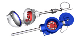
PRTD, CRTD, PRTD EX, or CRTD EX temperature sensor consists of one or several structurally-bonded primary temperature transducers, protective case, with or without mounting elements, and connecting device such as terminal head, box, connector or cable.
Thermocouple sensing element is a bifilar metal wire or meander film on insulating substrate. Sensing element has terminals for connecting wires. Electrical resistance is dependent on temperature.
For protection against mechanical effect, sensing element is put into protective casing.
Terms and definitions according to GOST 6651-2009
Resistance thermoelement measuring range:temperature range, in which resistance-temperature relationship rated in compliance with the existing standard takes place within the rage of corresponding tolerance class.
Resistance thermoelement operating temperature range:temperature range within measuring range or equal to it, for which the manufacture specifies reliability indices of resistance thermoelement.
Nominal resistance thermoelement application temperature:Resistance thermoelement operating temperature, which is standard for reliability and durability indices.
Nominal static characteristics: NSC:resistance thermoelement or sensing element resistance-temperature relationship, calculated by formulas for resistance thermoelement or sensing element with specific R0 value.
RT nominal resistance, R0, Ohm:resistance rated by the manufacturer at 0°С, rounded to whole values, indicated in marking and recommended from the following range: 10; 50; 100; 500; 1000 Ohm.
Technical specifications
1. Metrological characteristicsof temperature sensors PRTD, CRTD, PRTD Ex, CRTD Ex with electrical resistance output signal (with MT - code of field 9 at the table 1 is not filled) are given in the table 1.
Notes:
- all temperature sensors are initially calibrated after production. At customer's request sensor can be individually calibrated within temperature range 0 to 600°С;
Table 1
|
Temperature sensor type |
Tolerance |
Measurement range1, °С |
Permissible deviation limits from NSC, °С |
|
|
from |
to |
|||
|
CRTD |
A |
– 50 |
+120 |
± (0,15 + 0,002 · |t|) |
|
B |
– 50 |
+200 |
± (0,3 + 0,005 · |t|) |
|
|
C |
– 180 |
+200 |
± (0,6 + 0,005 · |t|) |
|
|
PRTD |
AA |
-50 |
250 |
± (0,10 + 0,0017 · |t|) |
|
A |
– 100 |
+450 |
± (0,15 + 0,002 · |t|) |
|
|
B |
– 196 |
+600 |
± (0,3 + 0,005 · |t|) |
|
|
C |
– 196 |
+600 |
± (0,6 + 0,01 · |t|) |
|
|
1 – limit values are given. Specific range depending on sensor modification and transmitter presence is given below on modification description pages, and is also given in sensor certificate and at the label. |
||||
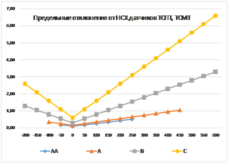
The picture given below compares tolerance limits of PRTD and CTx sensors without measuring transmitter.
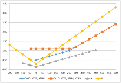
According to the picture, PRTD sensors of A tolerance class have minimal NSC deviation under temperature up to 300°С. For this range it is better to choose c0-class CTx sensors than to use B-class resistance thermometers according to GOST 6651-2009. To measure temperature values exceeding 300°С it is recommended to use c1-class CTx cable thermocouples, because they have less NSC deviation as compared to B-class resistance thermometers.
Nominal resistance R0
Table 2
|
Thermocouple version designation |
Pt |
P |
C |
|
Temperature coefficient a, °С-1 |
0.00385 |
0.00391 |
0.00428 |
|
Nominal resistance R0, Ohm |
100, 500; 1000 |
46, 50, 100 |
53, 50, 100 |
2. 4-20mА signal, digital signal via HART, Profibus, Fieldbus, WirelessHART
Measuring transmitter can be installed in terminal head. Measuring transmitter processes thermocouple signal to unified output DC signal according to GOST 26.011-80 4-20mA and/or digital signal via HART, PROFIBUS-PA, FOUNDATION Fieldbus. Sensors are available both with HART protocol of widely spread 5 version (package PR 5335) and with the recent version 7 (package PR 5337).
Temperature sensor with output DC signal and/or digital signal via HART, Profibus, Fieldbus with installed PR transmitter is an integral instrument. Its metrological characteristics are given in the table 3. It can be operated under climatic conditions specified in item 11.
Table 3
|
Temperature sensor type |
Output signal and |
Built-in |
Permissible intrinsic |
|
|
PRTD |
AAxH25, AxH25 |
4-20mА |
PR 5335 or |
0,25 % · tn or 0,3 °С |
|
AxH10, BxH10 |
0,1 % · tn or 0,15 °С |
|||
|
BxH70 |
0,7 % · tn or 1,0 °С |
|||
|
AxP25, AAxP25, |
Profibus PA, Foundation™ Fieldbus |
PR 5350 |
0,25 % · tn or 0,4 °С |
|
|
BxP70, BxF70 |
0,7 % · tn or 1,0 °С |
|||
|
AxF10, BxF10, |
0,1 % · tn or 0,15 °С |
|||
|
AA3T25; A3T25 |
4-20mА |
PR 5333 |
0,25 % · tn or 0,5 °С |
|
|
B3T70 |
0,7 % · tn or 1,0 °С |
|||
|
A3T40 |
PST-b-Pro |
0,4 % · tn or 0,5 °С |
||
Notes for Table 3:
а) tn = tmax – tmin, °С
where tmax and tmin are upper and lower limits of measuring range (stated in certificate and at sensor label).
b) Error limits are given for normal operating conditions and take into account the following errors: thermocouple (resistance thermometer) and intrinsic transmitter processing error.
c) «х» means number of wires in resistance thermometer connection diagram, х=3 or 4. For example, АА4Н25 or B3H7
d) At customer's request the sensor can be equipped with measuring transmitter produced by another manufacturer (Honeywell, E+H, Yokogawa and other). In this case it is necessary to take into account the following issues:
Sensor with measuring transmitter will not be an integral instrument having rated metrological characteristics. Sensor and measuring transmitter should be treated as two independent instruments having own metrological characteristics (similar to sensor and transmitter mounted on DIN-rail) and own permissible operating conditions. They should be calibrated separately according to methods approved for each of them. For measurement error analysis it is necessary to be ruled by GOST R 8.736 - 2011 "Multiple direct measurements. Measurement results processing techniques. Main principles".
See also item 15 concerning approval documents for such sensor.
Limits of permissible additional deviation caused by ambient temperature deviation from normal temperature (23 ± 5) °С for every 1°С, are given in the table 4.
Table 4
|
Output signal and |
Measuring range tn, °С |
Permissible additional error limits, °С |
|
T25, T40, T70 |
10 to 100 |
0.01 |
|
more than 100 |
0,01 %· tn |
|
|
H10, F10, P10, H25, P25, F25 |
10 to 100 |
0.005 |
|
more than 100 |
0,005 %· tn |
Resistance thermometer metrological characteristics inevitably change during operation. Change rate depends on several parameters, such as: operating temperature, temperature change rate and frequency, chemically active substances in measuring media, and other. According to these, operating conditions groups were determined for PRTD, CRTD, PRTD Ex, and CRTD Ex thermometers. Permissible metrological characteristics deviation are rated for every group of resistance thermometer.
Permissible deviation limits of thermocouple (resistance thermometer) metrological characteristics for in-use calibration interval should not exceed values given in the table 5.
Table 5
|
Type |
Tolerance class |
Application temperature, ° С |
Group of operating conditions |
Drift at CI, °С |
|
|
from |
to |
||||
|
CRTD |
A, B, С |
– 180 |
+200 |
II |
± (0,3 + 0,005 · |t|) |
|
PRTD |
A, B, С |
– 50 |
+300 |
I |
± (0,15 + 0,002 · |t|) |
|
AA |
– 50 |
+150 |
II |
± (0,1 + 0,0017 · |t|) |
|
|
150 |
250 |
III |
± (0,3 + 0,005 · |t|) |
||
|
PRTD |
A, B, С |
– 196 |
– 50 |
II |
± (0,3 + 0,005 · |t|) |
|
300 |
450 |
||||
|
450 |
600 |
III |
|||
|
t – temperature value |
|||||
Variation of thermocouple metrological characteristic should not exceed values given in the table 6.
Table 6
|
Lifetime, years |
Accuracy designation of temperature sensor with |
MT variation, °С |
|
2 |
H10, F10, P10, H25, P25, F25, H70, P70, F70 |
± 0,0010 · tn |
|
T25, T40, T70 |
± 0,0015 · tn |
|
|
5 |
H10, F10, P10, H25, P25, F25, H70, P70, F70 |
± 0,0025 · tn |
|
T25, T40, T70 |
± 0,0040 · tn |
4. Reliability measures
Temperature sensors are nonrepairable and nonrestorable items.
Temperature sensor reliability under operating conditions and modes specified by TU 4211-002-10854341-2013, is characterized by the following indices:
- failure-free operation probability;
- specified lifetime:
- average lifetime.
Temperature sensor reliability indices are specified in compliance with GOST 27883 and takes into account sensor operating conditions:
- application temperature;
- environment temperature and humidity;
- vibration and impact loads;
- media chemical attack on thermowell material.
Permissible parameter values for specific sensor modification can be seen in product certificate. Depending on parameters occurrence and level, operating conditions are divided in groups I, II, and III. These groups are given in the table 7.
Таблица 7 Temperature sensor reliability indices
|
Group of operating |
Probability of |
Calibration |
Mean lifetime |
|
I |
0.95 for 40 000 hours |
5 years |
10 years |
|
II |
0.95 for 16 000 hours |
2 years |
4 years (6 years) |
|
III |
0.95 for 8 000 hours |
1 year |
2 years |
Specified lifetime given in the table 12 is equal to calibration interval. If temperature sensor successfully passes periodical control, specified lifetime is prolonged for the following calibration interval.
The following situations are considered as sensor failure:
- permissible variation value excess during periodical or unscheduled control;
- protection fitting destruction or cable sheath integrity fault;
- discontinuity or short circuit of sensing element circuit;
- electrical insulation resistance value between sensing element circuit and metal part of protection fitting or cable sheath is lower than permissible value.
Mean lifetime is given according to failure-free operation probability equal to 0.8 for the specified period
Increased mean lifetime with 0.6 failure-free operation possibility for the given period.
5. Minimum insertion depth:
Table 8 Minimum insertion depth
|
Sensor type |
Sensor outer diameter, mm |
Sensor tolerance class |
Minimum insertion depth, mm |
|
PRTD |
3 |
АА, А |
15 |
|
В |
10 |
||
|
4; 5 |
АА, А |
30 |
|
|
В |
25 |
||
|
CRTD |
5 |
А |
55 |
|
В |
50 |
||
|
С |
50 |
||
|
PRTD |
6 |
АА, А |
35 |
|
В |
30 |
||
|
CRTD |
А |
60 |
|
|
В, С |
55 |
||
|
PRTD |
8 |
АА, А |
45 |
|
В |
40 |
||
|
CRTD |
А |
65 |
|
|
В, С |
60 |
||
|
PRTD |
10 |
АА, А |
65 |
|
В |
60 |
||
|
CRTD |
А |
80 |
|
|
В, С |
75 |
6. Electrical insulation resistance and insulation strength:
Table 9
|
Type |
Electrical insulation resistance |
Electrical |
||
|
DC |
Insulation |
Sinusoidal |
maximum leak current |
|
|
PRTD, CRTD |
100 V |
100 MOhm |
250 |
5 mА |
|
PRTD Ex, CRTD Ex |
500 |
5 mА |
||
7. Survey current
1 mA – nominal survey current for resistance thermometer with nominal resistance (R0) equal to 50 and 100 Ohm;
0,2 mA – nominal survey current for resistance thermometer with nominal resistance (R0) equal to 500 Ohm.
2 mA - maximum survey current.
8. Response time Response time is given below in performance specification for specific resistance thermometer modifications. Response time is described as a period of time require to change resistance thermometer indication at 63,2% of full change, under step change in medium temperature.
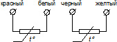
9. Wiring diagram and internal connector colour codes
Table 10
|
|
2-wire |
3-wire |
4-wire |
|
One |
|
|
|
|
Two |
|
|
|


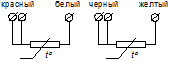
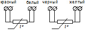
PRTD (CRTD) sensors with two-wire connection diagram can have only B or C tolerance class, and have limitations of mounting length and extension lead length. In compliance with GOST 6651-2009, inner wire resistance of two-wire sensors should not exceed 0,1% of nominal sensor resistance at 0°С. Due to this fact, various NSC have different mounting length limitations:
- maximum mounting length is equal to Lmax= (500÷1250)mm for sensors with terminal head depending on design modification,
- maximum length is equal to ℓmax= (500÷1000)mm for sensors with extension lead depending on design modification.
Tree- and four-wire connecting sensors relate to tolerance classes AA, A, B, or C depending on design modification. These sensors do not have limitations concerning mounting length and extension lead length. It should be taken into account, that secondary units, connected to sensors, can have limitations of input measuring line resistance, which, in turn, depends on sensor wire length.
10. Resistance to mechanical stress
.jpg) Sensors are resistant to sinusoidal vibration. Possible version groups - L1 to F3 - according to GOST R 52931-2008 depending on design modification (specific group is stated in specific modification description, and is also stated in sensor certificate). Reference vibration data according to modification groups is given in the table 11.
Sensors are resistant to sinusoidal vibration. Possible version groups - L1 to F3 - according to GOST R 52931-2008 depending on design modification (specific group is stated in specific modification description, and is also stated in sensor certificate). Reference vibration data according to modification groups is given in the table 11.
Table 11
|
Temperature sensor modification |
Vibration resistance groups according to GOST 52931-2008 (frequency range, acceleration, shift) |
Vibration resistance. |
Mechanical version group according to |
|
1хх, 2хх, 3хх |
V3 (10-150Hz, 49 m/s2, 0.35 mm) |
10÷150Hz, 5G |
М41 |
|
306 |
N2 (10-55Hz, -, 0.35 mm) |
10÷55Hz |
М6 |
|
205, 301, 302 |
F3 (10-500Hz, 49 m/s2, 0.35 mm) |
10÷500Hz, 5G |
М27 (М37) |
|
* - a group with the most severe operating conditions is specified. It is possible to use sensors in all |
|||
Cable resistance thermocouples without protection tube (modifications 105, 106, 206) are resistant to bending and can be wound on a cylinder, which radius is five times cable diameter, without performance change (in compliance with requirements of IEC 61515).
11. Climatic version
Ambient air temperature during operation
Table 12
|
Connection point designation |
Transmitter presence |
general purpose sensors |
Explosion-proof thermocouples |
|
|
temperature class according to |
||||
|
Т4 |
Т5…Т6 |
|||
|
14 to 19, 21, |
YES |
-55 ÷ +85 |
-55 ÷ +85 |
-55 ÷ +60 |
|
NO |
-60 ÷ +120 |
-60 ÷ +120 |
-60 ÷ +85 |
|
|
20, 22 |
YES |
-55 ÷ +85 |
— |
— |
|
NO |
-60 ÷ +120 |
— |
— |
|
|
10, 13 |
NO |
-40÷ +85 |
— |
— |
|
44, 45 |
YES |
-55 ÷ +85 |
-55 ÷ +85 |
-55 ÷ +60 |
|
NO |
-60 ÷ +120 |
-60 ÷ +120 |
-60 ÷ +85 |
|
|
50 to 59 |
NO |
-40 ÷ +200 |
-40 ÷ +135 |
-40 ÷ +85 |
|
60 to 69, 80 to 85 |
-60 ÷ +200 |
-60 ÷ +135 |
-60 ÷ +85 |
|
|
070, 071 |
-40 ÷ +350 |
— |
— |
|
|
002 to 005 |
-40 ÷ +200 |
— |
— |
|
12. Dust and water protection rate according to GOST 14254-96 and IEC 60529-89 corresponds to the values given in the table 13.
Table 13
|
Nominal |
Protection rate according to GOST 14254 |
Explanation |
|
000 to 005, 070, 071 |
IP40 |
Protection against foreign items, diameter >1 mm, without water protection |
|
10, 11, 13 |
IP55 |
Dust-proof. Protection against water jet from any side. |
|
20, 22, 050 to 069, 080 to 085 |
IP65 |
Dust-proof, Protection against water jet from any side |
|
14, 18, 19, 21, 23 to 29 |
IP66 |
Dust-proof, Protection against sea waves and strong water jets. |
|
15, 16, 17 |
IP66/IP68 |
Dust-proof, Protection against sea waves and strong water jets. Long-term immersion to the depth more than 1 m is possible. |
13. Seismic stability. 101, 102, 103, 105, 106, 107, 201, 202, 205, 206,300, 301, 302, 303, 304 modification sensors are earthquake-resistant:
¾ if it is installed directly on building structure - at grade 9 earthquake according to MSK-64, at 70 m installation level above zero mark;
¾if it is installed on intermediate structures (for example, on pipeline or reinforcement), or in complete plants as a built-in item - at grade 9 earthquake according to MSK-64, at 70 m installation level above zero mark (if there is no resonance within 1-30 Hz range at the place of item installation).
14. Marking
Thermocouple identification labels are made on metallized self-adhesive polyether film. Label material is temperature resistant within the range of –60 to +120°С, very resistant to solvents, UV, dirt.
15. Explosion-proof versions Exia, Exd of temperature sensors
Manufactured by PC TESEYfor PRTD, CRTD, PRTD Ex, CRTD Ex sensors (TU 4211-003-10854341-2013) can be installed at hazardous industrial facilities, as evidenced by Certificate of conformity to requirements of TR TS 012/2011 "On equipment operation safety in explosion hazardous areas" No. RU C-RU.GB06.В.00262 valid till 18.05.2019, issued by certification authority OS VSI VNIIFTRI ROSS RU.0001.11GB06.
PRTD, CRTD, PRTD Ex, and CRTD Ex temperature sensors should be used in compliance with requirements of existing normative documents:
- TR TS 012/2011 "On equipment operation safety in explosion hazardous areas";
- GOST 30852.13-2002 "Explosion-proof electric equipment. Part 14. Electric plants in explosion hazardous areas (except for underground workings)";
- "Electrical Installation Code" (EIC, chapter 7.3);
- "Regulations for operation of consumer electrical installations" (ROCEI, chapter 3.4);
- RE 4211-002-10854341-2013.
 Explosion protection type - explosion-proof sheath or intrinsically safe circuit ia. Explosion protection marking is given in the table below
Table 14
|
Temperature sensor version |
Explosion protection marking |
|
PRTD Exd, CRTD Ехd |
1ExdIICT4…T6 X |
|
PRTD Exi, CRTD Ехi |
0ExiаIICT4…T6 X |
If temperature sensor is equipped with measuring transmitter PR Electronics, it is a uniform instrument, and it is covered by the certificate of conformity TR TS 012.
If the customer wants to install measuring transmitted produced by another manufacturer, it is necessary to take into account the following information:
Normative documents have no clear instructions concerning prohibition or possibility to install certified MT with "intrinsically safe circuit i" explosion protection in sensor head and to specify explosion protection as 0ExiallCT6 X (similarly with sensor and measuring transmitter installed at DIN-rail). Sometimes enclosure to the certificate indicates not specific MT models, but their specification.
ATTENTION!In such situation a decision on measuring transmitter, other than PR, installation in Exi temperature sensor produced by LLC PC TESEY, shall be made by the customer! In this case LLC PC TESEY supplies two units as a set. Every unit has its own certificate, calibration certificate, and certificate of conformity. Measuring transmitter can be adjusted, calibrated and installed in sensor case if required.
16. Calibration is carried out:
Temperature sensor without measuring transmitter - according to GOST 8.461;
Temperature sensors with measuring transmitters - according to MP RT 2026.
17. Calibration interval (CI) depending on operation conditions groups is stated in
the table 7.
Operation guidelines
1. Specific temperature sensor fields of application stated in catalogue sections are given only as a reference, and can be extended by the consumer on condition that operating conditions at site correspond to technical parameters of the selected sensor modification.
2. Resistance thermometer installation, assembly and calibration during operation should be carried out in compliance with resistance thermometer technical description, operation manual RE 4211-003-10854341-2013, instructions for the equipment which is used together with the thermocouple. In explosion hazardous areas resistance thermometers should be used in compliance with specified explosion protection marking, and strict compliance to GOST 30852, 13-2002, PUE, PTEEP.
3. If resistance thermometer is installed in horizontal or inclined position without protective fitting, the customer should provide additional securing to prevent resistance thermometer bending and vibration during operation.
4. Resistance thermometer switching unit (heads, plugs, sleeves) workability depends on material, Тmax: 200°С – for terminal heads made of aluminium alloy; 150°С – for polymer terminal heads; 200°С – for adaptor sleeves. At temperature above 120°С a marking label, which identifies the product and its manufacturer, breaks, and at temperature above 150°С sealing gasket of terminal head can be broken.
5. If temperature sensor is used under vibrating conditions, or if it is required to improve response time, it is recommended to use 102, 108, 106 modification thermometers with thermowells and together with UNKJ 031, 038, 041 movable fittings instead of using 101 modification sensors. Specified modification guarantee good contact between sensor and thermowell, reduce response time, and also 2-3 times reduction of vibration if it exists.